Collection HDA hda-sl01@hongdapt.com Online message Site Map Hello, welcome to hongda spray-painting machine electric official website!
Sales of HONGDA spraygun We specialized in manufacturing electrostatic spray guns
+86 13622624429
+86 13622624429
Contact person: Ms Croesus
0769-81885105
Phone: +86 13622624429
E-mail: hda-sl01@hongdapt.com
Skype: hongdapt@outlook.com
QQ: 1550167687
Factory: Block A No336, Changqing North Road Chanan Town . dongguan China
Hotline:+86-13622624429
Operating manual
thank you for choosing our high-speed rotary atomizing electrostatic automatic spray gun product. In order to use this machine for a long time and always be able to use it under the best conditions.
Before using this machine, please read this user manual carefully. Especially, it is necessary to fully understand the various items, warnings, prohibitions, and precautions in the specifications and follow the correct usage methods.
The device mentioned in this user manual is intended for use in the painting industry. If personnel have not received correct guidance on the operation method and scope of use, and have not yet understood the operation method of the machinery, please do not use it.
Contents
1 、spray control system 5
2、HDA-605Y 6
3 、HDA-605R 7
4 、HDA-605straight 8
5 、HDA-605T 9
6 、Specifications 10
7、HDA-605Ystructure 11
8 、HDA-605Rstructure 12
9 、Straight tube structure 13
10 、T-shaped structure 14
11 、Three way valve structure 15
12 gear pump and paint spry system 16
13 、HDA-203Electrostatic controller panel 17
14 、 electrostatic controller black side 18
13 、Specifications 19
14 、HDA-205electrostatic controller 20
15 、Specifications 21
16 、 safety management 22
17 、 Operation Cautions 24
18 、Operation Cautions 25
19 、Operation Cautions 26
20 、Operation Cautions 27
21 、Confirmation items before homework 28
20 、Operation method 29
21 、maintenance 31
22 、Countermeasures for poor coating quality 32
23 、Fault handling 34
Scope Applicable to Products
The target product of this user manual is:
High speed rotating atomizing electrostatic automatic spray gun (model: HDA-605)
This product refers to a spray gun that is configured on an automatic coating production line with exhaust equipment, mainly used for electrostatic coating operations with rotary atomization, and can perform rotary atomization coating on adjusted coatings.
If you have any questions about the purpose or materials of use of this product, please contact our company. Without obtaining special permission from our company, any use under conditions other than those mentioned above is considered inappropriate and may result in accidents. Please take full note.
《General precautions for using this product》
1.Please do not use this product towards humans or animals. Otherwise, the presence of harmful substances can lead to severe symptoms such as inflammation or poisoning.
2.In the environment where this product is used, please frequently use ventilation devices and perform appropriate exhaust treatment to prevent harmful gases such as volatile organic solvents from being retained.
3.If any abnormal sounds, vibrations, or high-pressure leaks occur during the use of this product, please stop running immediately. If this product operates in an abnormal state, it may cause damage or even major accidents to the product.
4.Please do not use halogenated hydrocarbon solvents. Otherwise, the aluminum alloy contained in the components of this product may undergo a chemical reaction, which may cause an explosion.
5.Please do not bring spark generating devices such as matches or lighters, tools, etc. into the environment where the product is used. Otherwise, it may cause flammable substances to catch fire, leading to explosions and fires.
6.Before operating the open product, please confirm the assembly status of each machine to ensure that there are no damaged or missing components during operation.
7The coated object should always be kept grounded. Do not use paint hangers with poor conductivity. Before operation, it is necessary to confirm the grounding status of the conveyor, spray gun bracket, control system, and equipment marked as requiring grounding. If the grounding is poor, the static electricity carried by the coated object or painting fixture may cause spark discharge, leading to the occurrence of fire.
8. Please ground all conductive materials and thinner containers in the painting room. The entire ground should be covered with anti electrified structures below 1MQ and kept clean. If the grounding conductivity is poor, the static electricity carried on the conductor or diluent container may cause sparks and lead to a fire.
When cleaning or inspecting the rotary cup and components, please make sure to reduce the paint pressure and air pressure to zero, and cut off the power switch of the electrostatic controller before proceeding.
10. When cleaning the body or components of this product, please never use a metal brush. Otherwise, metal may cause damage to the body and components of this product.
11. Please do not immerse the attached hoses and cables of this product in diluent. Otherwise, it will damage the hoses and cables.
12. Do not place the connecting hoses and cables of this product directly on the ground. Use protective covers, protective tubes, or hang them on ceilings or side walls. Otherwise, hoses and cables may rub against the ground and cause damage.
13. The distance between the front end of this product (rotating cup front end) and the sprayed object must be at least 150mm (reference)
If the distance is not left within the specified range, the front end of the rotary cup and the sprayed object may generate arcing or overcurrent protection, causing the machine to malfunction.
14. When building this product as a system, please set up a secure chain mechanism. When the chain mechanism is activated, it is necessary to ensure that the high pressure, paint supply, air supply, cleaning solvent supply, etc. can be automatically stopped.
● Check for abnormal control
● Inspection of High Voltage Abnormalities
● Check for abnormal air pressure
● Check for abnormal rotation of the rotating cup
● Inspection of High Voltage Abnormalities
● Inspection of conductor grounding
● Inspection of ventilation and exhaust
1、spray system control
Please connect the signal input/output of the external controller, high-voltage module, rotary cup, oil supply system, as well as various paths such as air and paint according to the system control diagram shown in the following figure.
Please confirm the detailed specifications of each device for the connection operation of various power, air, and paint paths.
● Safety factors to be achieved when spraying water-based coatings: The correct installation method for high-voltage cables.
The high-voltage electrostatic controller comes with a discharge function and overcurrent alarm power-off function. Automatic discharge and discharge of fuel supply system C
(1) When opening the door to add paint, turning off the static electricity in the control cabinet will close the discharge cylinder, completely grounding the gear pump and paint container, and releasing them
Static electricity. Prevent sparks from causing fires when adding paint.
(2) When the high voltage is cut off, it will automatically discharge the remaining static electricity in 3-10 seconds.
![]()
![]()


During the normal operation of the equipment, the suction paint hose should not leave the liquid level of the coating, and should be completely in contact with the coating to prevent arcing
2 、HDA-605Y Electrostatic Rotating bell spray gun

3 、HDA-605R Electrostatic rotating bell spray gun
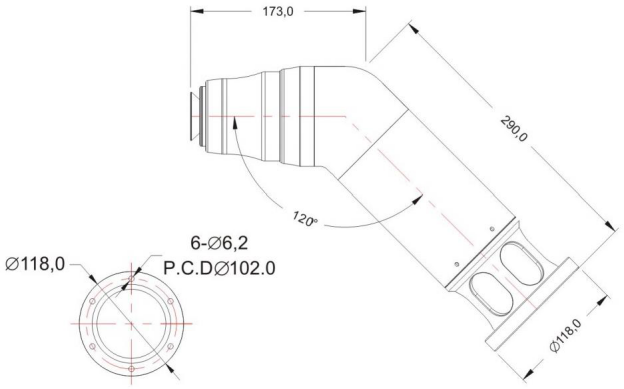

HDA-605 straight rotating bell spray gun


HDA-605T Electrostatic rotating bell spray gun


Specifications
No.
Item
Specifications
1
summary
Product name
HDA electrostatic rotating bell spray gun
Model
HDA605
application
Fixed spraying, reciprocating machine spraying, robot spraying
2
dimensions
P6/P7/P8
weight
Y-shaped: about 2 5kg R-type hollow type: about 3 5kg straight tube type: about 2.6kg
Excluding cables, pipes, and external brackets
3
※1)
Adapted paint, cleaning solvent
paint
Liquid paint(spray with resistance values below 10MQcm cannot be applied by electrostatic spraying.)
Waiter base paint(spraying insulation isolation device is required for spray with resistance value less than 1MQcm.)
cleaning solvent
Cleaning solvents with a resistance value of more than 20MQcm
4
environmental conditions
temperature
5℃~40℃
humidity
40%~80%
Spray room wind speed
0.3m/s~0.4m/s
5
Air conditions
Air bearing
100L/min(ANR) ※0.5MPa normal pressure:0.5MPa above
Air turbine
500L/min(ANR)(250L/min(ANR) ※40.000rpm unload)
Air forming
Forming air sprayed in the shape:750L/min(ANR)below
Max air pressure
Air hose:0.7MPa
Paint hose:1.0MPa
Air Supply quality
Solid particle size:0.1μm less Dew point under pressure :-20℃
Remaining paint amount :0.01mg/m3
6
Rotating speed
φ65mm bell cup :45.000rpm (under)
φ30mm bell cup:65.000rpm (under)
7
Electrostatic
voltage
Max. -80kV
Max. 120μA
※Please use it under the condition that the monitor current value is below 90μA
8
Spraying discharge volume
500mL/min(Viscosity 20sec/FC#4 under)
※This value is only a rough standard, and if the conditions exceed this range, you need to pass the coating test.
Confirm the quality of painting
HDA-605Y electrostatic rotating bell spray gun

No
Part code
Item
No
Part code
Item
①
HDA-Y0001
Front cover
②
HDA-Y0002
分配盘
③
HDA-Y0003
Bell cup
④
HDA-Y0004
Forming ring
⑤
HDA-Y0005
Forming part
⑥
/
Screw M4
⑦
HDA-Y0006
Forming seat
⑧
HDA-Y0007
Motor housing
⑨
HDA-Y0008
Air bearing
⑩
HDA-Y0009
magnet ring
⑪
HDA-Y0010
main shaft
⑫
HDA-Y0011
Stainless nozzle
⑬
HDA-Y0012
Seal ring
④
HDA-Y0013
Drive seat
⑤
HDA-Y0014
Y bracket
⑥
HDA-Y0015
Back cover
HDA-605R electrostatic rotating bell spray gun

|
No |
Part code |
Item |
No |
Part code |
Item |
|
① |
HDA-R0001 |
Front cover |
② |
HDA-R0002 |
分配盘 |
|
③ |
HDA-R0003 |
Bell cup |
④ |
HDA-R0004 |
Forming ring |
|
⑤ |
HDA-R0005 |
forming part |
⑥ |
/ |
Screw M4 |
|
⑦ |
HDA-R0006 |
Forming seat |
⑧ |
HDA-R0007 |
Motor housing |
|
⑨ |
HDA-R0008 |
Air bearing |
⑩ |
HDA-R0009 |
magnet ring |
|
⑪ |
HDA-R0010 |
main shaft |
⑫ |
HDA-R0011 |
Stainless nozzle |
|
⑬ |
HDA-R0012 |
Seal ring |
④ |
HDA-R0013 |
Drive seat |
|
⑤ |
HDA-R0014 |
fixing ring |
⑥ |
HDA-R0015 |
flange base |
|
⑰ |
HDA-R0016 |
Elbow shaped bend |
8 |
HDA-R0017 |
straight housing |
|
⑲ |
HDA-R0018 |
Flange connectors |
|
|
|

|
No |
Part code |
Item |
No |
Part code |
Item |
|
① |
HDA-L0001 |
Front cover |
② |
HDA-L0002 |
分配盘 |
|
③ |
HDA-L0003 |
Bell cup |
④ |
HDA-L0004 |
Forming ring |
|
⑤ |
HDA-L0005 |
forming part |
⑥ |
/ |
Nut M4 |
|
⑦ |
HDA-L0006 |
Forming seat |
⑧ |
HDA-L0007 |
Motor housing |
|
⑨ |
HDA-L0008 |
Air bearing |
⑩ |
HDA-L0009 |
magnet ring
|
|
⑪ |
HDA-L0010 |
spindle |
⑫ |
HDA-L0011 |
stainless nozzle |
|
⑬ |
HDA-L0012 |
O ring |
④ |
HDA-L0013 |
Drive seat |
|
⑤ |
HDA-L0014 |
Outer housing |
⑥ |
HDA-L0015 |
Fixing rod |
|
⑰ |
/ |
Plastic nut |
8 |
HDA-L0016 |
flange base L |
|
⑲ |
HDA-L0017 |
Holding rod |
0 |
HDA-L0018 |
Black cover L |
|
② |
HDA-L0019 |
PG joint |
|
|
|

|
No |
Part code |
Item |
No |
Part code |
Item |
|
① |
HDA-T0001 |
Front cover |
② |
HDA-T0002 |
分配盘 |
|
③ |
HDA-T0003 |
Bell cup |
④ |
HDA-T0004 |
Forming ring |
|
⑤ |
HDA-T0005 |
forming part |
⑥ |
/ |
Nut M4 |
|
⑦ |
HDA-T0006 |
Forming seat |
⑧ |
HDA-T0007 |
Motor housing |
|
⑨ |
HDA-T0008 |
Air bearing |
⑩ |
HDA-T0009 |
magnet ring |
|
⑪ |
HDA-T0010 |
spindle |
⑫ |
HDA-T0011 |
stainless nozzle |
|
⑬ |
HDA-T0012 |
O ring |
④ |
HDA-T0013 |
Drive seat |
|
⑤ |
HDA-T0014 |
T holding rod |
⑥ |
HDA-T0015 |
PG joint |

|
No |
Part code |
Item |
No |
Part code |
Item |
|
① |
HD-SXF000308 |
Pint in |
② |
HD-SXF000310 |
Air pressure |
|
③ |
HD-SXF000101 |
seat |
④ |
HD-SXF000301 |
seat |
|
⑤ |
HD-SXF000201 |
seat |
⑥ |
HD-SXF000305 |
valve core |
|
⑦ |
HD-SXF000303 |
Teflon Seat |
⑧ |
/ |
Nut |
|
⑨ |
/ |
joint |
⑩ |
HD-SXF000306 |
valve core seat |
|
⑪ |
HD-SXF000302 |
Sealing diaphragm |
⑫ |
HD-SXF000307 |
Valve core fixed seat |
|
③ |
HD-SXF000311 |
Spring fixed seat |
④ |
/ |
sealing |
|
⑤ |
HD-SXF000312 |
piston |
⑥ |
/ |
O ring |
|
⑰ |
HD-SXF000313 |
O ring |
⑱ |
1 |
Nut |
|
⑲ |
/ |
joint |
0 |
/ |
Nut |

|
No |
Part code |
Item |
No |
Part code |
Item |
|
① |
HD-90010088 |
Diver motor AC220V Reducing12.5:1 |
② |
HD-CLB003101 HD-CLB003102 |
Plum blossom coupling Shrapnel coupling |
|
③ |
HD-Q00070 |
connecting rod |
④ |
/ |
Gear pump Paint/IN |
|
⑤ |
/ |
Gear pump paint/IN |
⑥ |
/ |
Gear pump body |
Attention: Due to equipment improvements and other reasons, the shape and specifications of this machine may change without prior notice
HDA-203 Electrostatic control panel
< front Panel >

|
No |
Item |
No |
Item |
|
① |
Power ON/OFF |
② |
Electrostatic ON( manual) |
|
③ |
Electrostatic display |
④ |
Electrostatic voltage indicator |
|
⑤ |
Current display |
⑥ |
Abnormal current indicator |
|
⑦ |
Electrostatic voltage control |
|
|
Attention: Due to equipment improvements and other reasons, the shape and specifications of this machine may change without prior notice
Electrostatic control panel back side

No
Name
description
①
AC G R
H.V power pack
HV 12V
Receive high voltage start signal
OC 12V
Fault output DC12V
②
Power port
220V
Attention: Due to equipment improvements and other reasons, the shape and specifications of this machine may change without prior notice
Specifications
Item
Description & data
name
electrostatic spray system
model
HDA-203
Safety device
Current (absolute value) detection circuit breaker (OCL)
H. V charge
(remote signal)
Through remote and closed signals
Rated current
80μA(35kV)
short-circuit current
80μA±10μA
Output voltage adjustment
10-100KV
Transmission voltage
AC24V±2V
Transmission frequency
20kHz±1kHZ
使用条件
Temperature O~45℃
Humidity 20~85%(无结露)
gas composition
No corrosive gases, dust, steam, water droplets falling, direct sunlight exposure, etc
IP Grade
IP43
Power input
AC210-240V
frequency
50/60Hz
power capacity
50VA
Weight
约4.0Kg
HDA-205 electrostatic control unit

Specifications
|
name |
Description & data |
|
model |
electrostatic spray system |
|
Safety device |
HDA-205 |
|
H. V charge (remote signal) |
Current (absolute value) detection circuit breaker (OCL) |
|
Rated current |
Through remote and closed signals |
|
short-circuit current |
80μA(35kV) |
|
Output voltage adjustment |
80μA±10μA |
|
Transmission voltage |
10-100KV |
|
Transmission frequency |
AC24V±2V |
|
使用条件 |
20kHz±1kHZ |
|
gas composition |
Temperature O~45℃ Humidity 20~85%(无结露) |
|
IP Grade |
No corrosive gases, dust, steam, water droplets falling, direct sunlight exposure, etc |
|
Power input |
IP43 |
|
frequency |
AC210-240V |
|
power capacity |
50/60Hz |
|
Weight |
50VA |
|
name |
Around 5.0Kg |
safety management
For the safety of the operation and the long-term use of the spraying machine, please pay attention to the following matters not only during the operation process, but also before and after the operation:
(1) The controller must be grounded.
The grounding wire of the controller is the foundation of safe operation. The grounding wire of the spraying machine is also taken from the controller, so it is necessary to determine the grounding wire.
(2) The coated workpiece should always be kept grounded
The coated workpiece is usually grounded by a conveyor, but if there is paint attached to the contact part of the lifting device, it will cause poor conductivity, and the coated workpiece will be charged, which is prone to sparks and can become a cause of fire. Therefore, it is necessary to regularly remove the paint attached to the lifting equipment.
(3) All metal objects in the painting room should be grounded.
Due to high voltage in the painting room, the air around the spraying machine ionizes, and there is a risk of sparking when ungrounded metal objects become charged. Therefore, metal objects such as spray painting machine installation platforms or safety barriers in the painting room should be securely connected to the ground wire. Do not place unused metal objects such as paint cans and tools in the painting room.
Even if the solvent container is placed near the entrance and exit of the painting room, it should be grounded.
(4) The ground for painting operations requires anti electrified structures. When a closed painting room is used, the entire floor is required. When an open painting room is used, it is required that the range of 1.5m on both sides of the opening and 2.5m in front of it includes an anti charge structure below IMQ, and it is required to maintain cleanliness.
(5) When cleaning the atomizing cup, the power switch of the control box must be turned off and the front grounding wire must be connected before proceeding. If high-voltage electricity occurs during the cleaning of the atomizing cup, it can become a cause of fire. The power switch must be turned off when the homework is interrupted or completed.
(6) Do not use metal brushes when cleaning the atomizer cup
The atomizing cup is the life of the coating machine. If the metal brush is used, the atomizing cup will be damaged and the uniform spray state will not be obtained, so please use the attached brush.
(7) The spraying machine body, power cables, and hoses should not be immersed in solvents.
Electrostatic spraying machine is an electrical machinery, and soaking it in solvents can become a cause of malfunction.
(8) Do not drag power cables and hoses on the ground, try to hang them on the ceiling or wall. When using conductive coatings, insulation materials such as rubber hoses should be used to hang the coating hoses. If cables and hoses are dragged on the ground, they are prone to damage.

The atomizing cup is a precision component, please keep it clean regularly and avoid excessive tightening and damage.
Metal containers should be used for cleaning solvents inside the painting room, and resin materials should not be used as the base plate for painting room.
(9) The painting room and exhaust system (ventilation ducts, exhaust fans) should be kept clean and regularly cleaned.
In case of a fire, the volatile gases from the paint in the painting room and exhaust system will become combustibles, and the disaster will be even greater.
(10) The condensed water from air filters, air compressors, etc. should be fully discharged.
If there is moisture in the air, it can cause the alarm to sound and the safety circuit to operate due to poor spraying. Therefore, great attention should be paid to removing moisture.
(11) The distance between the front end of the atomizing cup and the coated workpiece must be kept at least 150mm.
In terms of structure, the potential of the atomizing cup of the electrostatic spraying machine usually decreases automatically when it approaches the ground wire. But when insulating paint pumps (such as metal coatings, woodworking coatings, water-soluble coatings, etc.), the potential of the pump will not decrease, and there is an inherent possibility of large sparks.
Considering unexpected situations such as swinging and falling of the coated workpiece, it is necessary to maintain sufficient spraying distance for the operation.
(12) When using an insulated table, it should be kept at least 500 mm away from surrounding objects. When touching, the power supply of the control box must be cut off and grounded before touching.
Coatings with low resistance values pose a risk of electric shock when in contact with paint containers, just like electrical wires. Places facing the pathway,
Grounded safety barriers must be installed to avoid misunderstandings among general workers. To prevent any unforeseen circumstances, it is necessary to keep fire extinguishers on hand.
(13) Check the air and paint for leaks before use. Even during use, it is important to regularly check for loose screws to avoid accidents.
(14) When using and setting up this device, it is necessary to comply with current regulations.
[Labor Safety and Health Regulations, Safety and Health Measures for Electrostatic Spraying]
Precautions for operation

Please be sure to follow the following steps when operating the air spindle.
If there are errors in the homework, the air bearings may be damaged, unable to fully perform, and even cause damage. In addition, the spindle part is in a high-speed rotating state, which poses a risk of injury. Please pay full attention.
1) Please make sure to confirm whether the spindle part is in an unrotated state before starting the operation. Even when rotating at low speeds, do not directly touch the rotating cup with your hands to stop the rotation.
The main shaft will continue to rotate even after the turbine air is turned off due to the influence of inertia. Moreover, even when displayed as "Orpm" on the monitor, it may rotate at around 100rpm. In this case, touching the rotary cup or spindle with your hand may result in injury. Therefore, during the inspection, please make sure to confirm whether the rotating cup and spindle have indeed come to a complete stop.
2) When introducing turbine air, please make sure to confirm whether the pressure of the bearing air is above 0.5 MPa and whether the main shaft can be easily rotated by hand.
If the distance of the turbine air supply path is long, please increase the diameter of the hose to reduce pressure loss.
3) When installing or disassembling the rotary cup, please be sure to clean the conical (female) part of the rotary cup on the inside of the spindle to keep it free of paint
The attached state.

If a cup stained with paint is installed and the spindle is rotated, it may cause damage to the air bearing.
4) During the operation of the solenoid valve for coating valve ON-0FF, please make sure to activate the interlock mechanism so that the coating valve can automatically turn off when the turbine speed reaches below 10.000rpm.5)在作业结束When stopping or interrupting the air source of the air disc, please make sure to stop the turbine air and confirm that the main shaft has not rotated after more than 3 minutes. If the bearing air is stopped during inertial rotation, it will damage the air spindle.
6) When manually stopping the turbine air, it is necessary to confirm whether all paint valves are in the "closed" state or whether there is no aerosol coming out of the rotary cup before implementing the stop operation.
Precautions for operation
Repair of air spindle
If the air spindle is installed and used correctly, it can achieve semi permanent stable high-speed rotation.
However, if it is found that even if air is injected into the bearing, the spindle cannot be easily rotated by hand and the speed cannot increase, it needs to be replaced with a new product or repaired. In case of repair, please send it back to our company.
|
A Attention |
|
As the air spindle is composed of very precise components, any malfunctions that occur during repair or disassembly at a repair factory not designated by our company will not be covered by the warranty. Please take note |
② Rotating bell and shaped air cover
(1) Installation and disassembly
When installing or disassembling the rotary cup, please confirm whether the rotation of the main shaft has completely stopped while supplying air to the bearing before proceeding. In addition, it is necessary to confirm whether the output of the high-voltage generator for static electricity is in the OFF state.
1) After confirming that there is no paint dirt on the conical surface of the spindle, please use a special tool wrench to hold the spindle, then install the spray cup onto the spindle and screw it in by hand for installation.
2) Please do not use tools other than adjustable wrenches for installation. If the rotary cup is damaged or deformed, please replace it with a new one
(2) Operation of rotating bell
This painting machine uses precision air bearings.
In addition, the rotating cup installed on the air bearing is usually used in the ultra-high speed rotation state of 20000~40000 rpm. Therefore, if the operation method is incorrect, it may cause the rotating cup to be unbalanced, resulting in significant damage to the air bearing.
In order to consistently achieve stable performance, please regularly check the following items before starting or after completing the task.
1) When installing the rotary cup, please use tools such as needles (below 0.8 diameter) to pass through the coating hole of the rotary cup and confirm whether the coating hole is blocked.
2) The conical part used for centering the rotary cup and spindle, both of which need to be kept in a state of no paint adhesion at all times.
Operational precautions
△ Attention
If paint or dirt adheres to the conical part, and the spin cup is installed and used, the rotation will become unbalanced. At this time, if the air spindle is rotated at high speed, it may cause damage to the air spindle.

Confirm if there is indeed no dirt attached
3) When disassembling the rotary cup, please use a cloth or other tool to wipe the paint attached to the paint nozzle clean. Please also be careful not to attach paint to the tapered part of the spindle at this time.
4) The working time of the rotary cup is generally 8 hours as the standard. At the end of the operation, please be sure to clean it with a diluent with good solubility, blow dry the inside and outside, and then check whether the cone surface and coating holes are clean and undamaged.
5) When immersing the rotary cup in diluent, please do not place it overlapping to make it in contact with each other. Also, please place the edge of the rotating cup facing downwards and carefully.
|
Attention |
|
When the spin cup falls or collides with other items, please make sure to replace it with a new one. If the bell jar deforms, the rotation will become unbalanced. If the bell jar is then rotated at high speed through the air spindle, it may cause damage to the air spindle. |
The scratches and other damages on the edge of the rotary cup may affect the micronization performance. If any damage is found, please replace it with a new
Precautions for operation
① Cleaning operation at the end of painting
(1) Cleaning of spray gun body
1) In the assembled state of the rotary cup and air cap kit, please use a cloth containing diluent to carefully wipe the protective cover of the spray gun body.
2) When the dirt is difficult to remove, please remove the cover, immerse it in the diluent for a few minutes, and then wipe it with a cloth (please do not soak it in the diluent for a long time)
|
Attention |
|
Please do not rub the surface of the spray gun with tools such as brushes or peelers. If the surface is damaged, dirt will easily adhere in the future. In this way, along with the coating dirt on the surface, static electricity at the front end of the spray gun is easily missed to the grounding part, which may cause abnormal static electricity. |
|
! Warning |
|
If inhaled or in contact with a substance containing paint and solvents, it will be harmful to the human body. Therefore, please work in a well ventilated area to prevent the accumulation of harmful substances. |
(2) Cleaning of formed air hood nozzle and rotary cup
1) Please use diluent to clean the coating path inside the spray gun.
2) Confirm whether the high-voltage generator for static electricity is in the "OFF" state, use a grounding rod to remove the electricity, remove the cap, and then use a special wrench to remove the rotating cup.
3) Please clean the rotary cup thoroughly with diluent. If the paint is stuck and cannot be cleaned, immerse it in a clean diluent and then use a brush or other tool to wash off the paint.
4) At this point, please use a cloth containing diluent to wipe off the dirt on the cone surface of the air spindle and the front end of the feeding tube.

5) Please clean the surface of the formed air cover with diluent. If the dirt is severe, please disassemble the air cap kit and clean its internal components together.
6) Please use a soft brush, brush, etc. with a vine thinner to clean the air vent holes of the air hood kit. Finally, perform a blow drying process to remove any remaining paint residue, diluents, etc. inside.
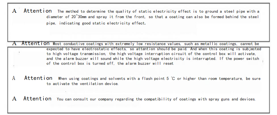
Confirmation items before operation
1.Mixing of paint
Except for some coatings, most synthetic resin coatings in this device can achieve electrostatic effects, so there is no need for special blending. But sometimes in order to achieve higher electrostatic effects, the solvent needs to be adjusted according to the situation.
Some coatings with extremely low resistance values cannot achieve the expected electrostatic effect. Use a paint resistance meter to confirm the paint resistance value. When adjusting the resistance value of the coating to 15~70MQ-CM, good results can be obtained in most cases. (Different measuring instruments result in different parameter values)
2.Inspection of Automatic Spinning Cup Electrostatic Gun
(1) Install the atomizing cup onto the spindle and tighten it by hand, then lock the forming cover onto the main body.
2.Inspection of Automatic Spinning Cup Electrostatic Gun
(1) Install the atomizing cup onto the spindle and tighten it by hand, then lock the forming cover onto the main body.
|
A Attention It is necessary to confirm the locking, otherwise loosening may occur during high-speed rotation. |
(2 Start the gear pump to put the paint into the paint bucket and suck it up to the three-way valve of the spray gun, which returns to the paint bucket through the return pipeline. Set parameter value size
![]() (3)Turn on the speed (pressure of about 2kgcm2) and forming (pressure of about 1.5-3kg) air to the pneumatic motor. After the speed stabilizes, turn on the paint switch for about 5 seconds, and the paint will be sprayed out from the front end of the spray gun. (Speed and pressure should not exceed 4kg)
(3)Turn on the speed (pressure of about 2kgcm2) and forming (pressure of about 1.5-3kg) air to the pneumatic motor. After the speed stabilizes, turn on the paint switch for about 5 seconds, and the paint will be sprayed out from the front end of the spray gun. (Speed and pressure should not exceed 4kg)
![]() A Attention To use a rotary cup electrostatic gun, the speed and forming must be turned on first before turning on the paint switch, otherwise the paint may pour back into the rotary cup and cause damage.
A Attention To use a rotary cup electrostatic gun, the speed and forming must be turned on first before turning on the paint switch, otherwise the paint may pour back into the rotary cup and cause damage.
(4) Confirm the spraying of paint, adjust the required amount of paint spraying, and set the air pressure for speed forming. Activate the electrostatic switch, and when high voltage static electricity is generated, the controller (HDA-203) KV (red) light will turn on, setting the output high voltage level. When the red light is on, high voltage static electricity is generated at the front end of the spray gun.
Attention When the inspection is completed, the electrostatic switch of the power supply of the electrostatic controller (HDA-203) needs to be turned off.
Operation method
1.Preparation for spraying operation
(1) Put the paint into the paint supply device
When using this machine, the standard viscosity is generally 9-30 seconds/FC # 4, but various conditions such as the shape of the coated workpiece and the thickness of the coating are not necessarily limited depending on the type of coating and solvent. In addition, before placing the coating, it is necessary to measure the coating resistance value.
(2) Activate the paint supply device (gear pump) and send the paint to the three-way valve return pipeline of the spray gun for oil discharge to the paint bucket.
(3) confirm again that the controller power static switch is turned off.
(3) Turn on the rotating cup electrostatic spray gun speed and molding air to spray the coating oil spray gun
Confirm that the rotating cup electrostatic spray gun speed and forming air have been started. After the rotating cup speed stabilizes, turn on the paint switch and spray atomization for about 10 seconds. If there is residual air in the paint hose, the paint spraying will be intermittent. You can start the paint device to circulate until there is no residual air in the pipeline. The size of the paint spraying amount is set as a parameter value on the paint control panel.
2、Spray painting operation begins
(1)Set the discharge volume and reciprocating machine speed, ground rail chain speed, activate the controller's electrostatic start, and the red light will turn on
The front end of the spray gun already has a high-pressure output
Attention
Before turning on the power switch of the controller, please confirm whether the controller is grounded in advance.
(2)Please input the automatic setting conditions to start the operation. The controller can be adjusted between 20-60KV (manually).
(3) When adding paint midway (interrupted), be sure to turn off the static switch and the paint switch. After using a discharge rod (grounding device) to release the residual charge of the paint pump, add or stir the paint. After completion, turn on the paint switch and start the electrostatic operation. After finishing the spraying operation, the electrostatic switch must be turned off.
Attention
When the resistance value of the coating is low (below 2M-cm), place the coating pump on an insulated platform for use.
At this point, the paint pump is being charged by high voltage electricity. It is absolutely forbidden to come into contact with the paint pump during high voltage electricity output. If it is necessary to come into contact with or supplement the paint, the static electricity output must be cut off first and discharged with a grounding rod.
3、Disposal after homework completion
(1) Turn off the static switch of the controller (O FF).
(2) Release the residual charge of the paint pump with a grounding device, lift the oil suction pipeline, and operate the pump to flow out the residual paint in the paint pipeline through the reflux pipe.
(3) The paint in the paint pipe is returned. Place the oil suction pipeline in the cleaning solvent and suck it up to the three-way valve group of the spray gun until it returns to the return pipeline. (Confirm that the speed and forming air are in the open state) Start the paint switch for 10-15 seconds, clean the three-way valve to the front end of the spray gun atomization cup, clean the atomization cup, and then perform pipeline circulation cleaning.
(4) For two-component chemical hardening coatings, when circulating the pipeline for cleaning, the reflux pipeline should return the solvent back to another container to avoid solvent contamination and incomplete cleaning.
(5) After returning the solvent, turn off the rotation speed and open pressure of the rotary cup. After the rotary cup stops rotating, remove the forming cover and atomizing cup, clean them with solvent, wipe them with a soft brush or cloth, and then reinstall them for use.
Attention
When cleaning the spray gun, it is necessary to confirm that the static switch is turned off and grounded to release the charge for 10 seconds before proceeding. More than 90% of fires caused by using the static spray gun spraying machine occur during cleaning, so the power must be turned off. In addition, to prevent
When cleaning the atomizing cup and forming cover, they can be soaked in solvent, cleaned with a soft bristled brush, blown with compressed air, and never pierced with hard objects such as metal wires.
Attention
If there are any abnormalities in the homework, please immediately turn off the static switch and power, turn off the paint switch, and turn off the speed and forming pressure.
Attention
If not used for a long time, please clean 2-3 times with clean cleaning solvent. For the last cleaning, use a solvent mixed with paint to circulate the gear pump to the spray gun pipeline.
Some manufacturers have different quality of cleaning solvents and mixed coating solvents. Please use mixed coating solvents for the final cleaning.
Maintenance
1.atomizing bell cup
(1)carefully clean the atomizing cup and forming cover each time when finish work.
(2)When cleaning blockages, do not use metal such as iron wire to puncture. Soak in solvent first and then blow with compressed air. Do not use metal brushes.
(3)When using two-component chemical coatings, they must also be cleaned during each color change. Coatings attached to the cup can cause poor atomization and affect the effect。
(4)The spray gun protective cover should be kept clean regularly, wiped with a cloth dipped in solvent, and then dried with compressed air.
(5)Except for faults, it cannot be disassembled casually. To ensure the high-speed stability of the spray gun, it is best to use the atomizing cup one-on-one without exchanging it。
2. The paint hose and power cable
(1)Keep clean and do not attach paint or other debris.
(2)Do not subject it to mechanical impacts (such as trampling, pressing objects, and rolling).

Please turn off the power supply of the controller and turn off the speed, forming, and coating switches during maintenance or repair。
A Be sure to ground the conductive container during cleaning.
Paint problem & solution
According to the situation of poor spraying, there are multiple adverse phenomena occurring simultaneously. 1. The spray is poorly micronized.
|
reason |
solution |
|
(1)The forming air pressure is insufficient. |
(1)Increase the forming air pressure. |
|
(2)Excessive discharge of paint。 |
(2)Reduce the amount of paint sprayed or increase the forming air pressure. |
|
(3)The viscosity of the coating is too high. |
(3)Reduce the viscosity of the coating. |
|
(4)The atomizer cup is damaged. |
(4)replace the bell cup |
Excessive rebound of paint
|
reason |
solution |
|
(1)Spray distance too long. (2)High forming air pressure. (3)Incomplete grounding of the coated workpiece. (4)The exhaust speed is too slow |
(1) Operate at a spraying distance of 150-200 ITlm. (2)Reduce the pressure of the forming air. (3) grounding complete (4)Accelerate the exhaust speed. |
Low painting rate
|
reason |
solution |
|
(1)Poor grounding of the coated workpiece. (2)The forming air pressure is too high for atomization. (3)The spraying distance is too long. (4)The supply voltage is too low. (5)The exhaust speed is too fast. |
(1) Remove the paint attached to the tool and make it fully grounded. (2)Adjust the forming air pressure appropriately. (3) Operate at a spraying distance of 150-200m. (4) Raise the output voltage on the controller. (5) Slow down the exhaust speed. |
4. The nozzle may have filamentous foreign objects attached to the coating or filamentous foreign objects on the coated workpiece.
|
reason |
solution |
|
(1)The viscosity of the coating is too high. |
(1)Reduce the viscosity of the coating. |
When sand particles appear on the sprayed surface
|
reason |
solution |
|
(1)Poor atomization of spray coating. (2)There is dust in the spraying room and dust adhering to the spraying surface. (3)Atomized air pollution. (4)Poor dispersion of pigments in coatings. |
(1)Please refer to Item I "Poor Particularization of spray" in this chapter. (2)Install a dust removal and filtration device at the suction port of the spraying room to remove dust from the spraying surface. (3)Clean or replace the filtering device in the air passage. (4)Thoroughly consider the coating. |
The membrane has an orange peel surface
|
reason |
solution |
|
(1)The temperature inside the spraying room is high. (2)The temperature of the coated workpiece is too high. (3)The suction and exhaust are too fast |
(1)Adjust the room temperature. (2)Adjust the drying furnace to reduce the temperature of the coated workpiece. (3)Adjust the surface of the coated workpiece to 0.5-1.0m/SEc. |
Rebound phenomenon
|
reason |
solution |
|
(1)The coated workpiece is not clean enough. (2)Pollution caused by atomized air. |
(1)Thoroughly clean and degrease. (2)Clean or replace the filtering device in the air passage. |
Dripping paint on the sprayed surface
|
reason |
solution |
|
(1)The coating is too thick. (2)The viscosity of the coating is too low. (3)The humidity inside the painting room is too high. |
(1)Reduce the amount of discharge or increase the operating speed of the spray gun. (2)Increase the viscosity of the coating. (3)Adjust humidity with air conditioning or other devices. |
Thin coating
|
reason |
solution |
|
(1)The amount of paint ejected is small. (2)The viscosity of the coating is too low. |
(1)Adjust the amount of paint sprayed and the running speed of the spray gun, and consider repeated spraying. (2)Increase the viscosity of the coating. |
Pores (small holes) occur
|
reason |
solution |
|
(1)Pollution caused by atomized air. |
(1)Clean or replace the filter in the air passage. |
|
(2)The temperature of the coated workpiece is too high. |
(2)Reduce the temperature of the coated workpiece. |
|
(3)Insufficient drying of primer. |
(3)Fully dry. |
|
(4)Set the time to be short. |
(4)Adjust the set time. |
White patches appear
|
reason |
solution |
|
(1)The temperature and humidity inside the spraying room are high. |
(1)Check the air conditioning equipment. |
Bubbling
|
reason |
solution |
|
(1)Pollution of formed air. (2)Insufficient drying after washing with water. (3)The coating is too thick. (4)The temperature of the drying oven is too high. |
(1)Clean the air passage filter or replace it. (2)Fully dry. (3)Reduce the amount of paint sprayed. (4)Adjust the temperature to an appropriate value. |
Poor spray pattern shape
|
reason |
solution |
|
(1)The forming air holes and paint spraying ports of the forming cover have paint or dust attached. |
(1)Use a brush dipped in solvent to thoroughly clean and filter the coating. |
|
(2)The viscosity of the coating is high. |
(2)Reduce viscosity. |
|
(3)The front end of the atomizer cup is damaged. |
(3)Repair or replace. |
|
(4)Poor adjustment of spray amplitude. |
(4)Adjust with a spray amplitude regulator valve. |
|
(5)Poor installation of atomizing cup. |
(5)Confirm if the atomizing cup is loose and assemble the air cover coating. |
problem & solution
paint output poor
|
reason |
solution |
|
(1)Gear pump is worn out during normal use (2)The paint hose and valve group have cured paint (3)The paint outlet of the atomizing cup has solidified coating |
(1)Adjust the setting parameters of the gear pump (2) Clean the pipeline and three-way valve group (3) Remove the atomizing cup and clean |
Atomizing bell cup paint dripping
|
reason |
solution |
|
(1)The three-way valve cannot be closed (2)Uncontrolled switch paint and air pressure |
(1)Remove the three-way valve and clean the internal pint out port (2)check out the pint On/Off control system |
Electrostatic control warning
|
reason |
solution |
|
(1) bell gun leakage (2) paint resistance poor (3) H.V pack leakage (4) electrostatic cable damaged |
(1) clear the bell gun front cover (2)adjust paint output or reduce the pressure (3) replace the H.V pack (4)replace the power cable |